Electronics · 2026
Elektra dalje
A society medal with the Elektra logo in eighteen addressable LEDs. My first PCB, and an exercise in hiding an ESP32, a LiPo charger and a latching power switch behind a face that had to stay empty.
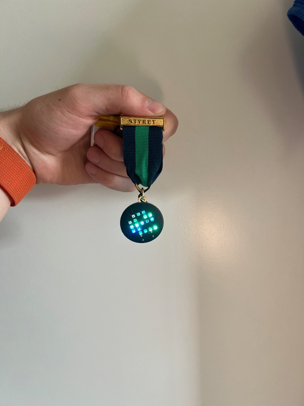
A dalje is a small medal worn on formal dress in Norwegian student culture. You get one when you join a linjeforening (the society for your degree programme), and you collect more from other societies' galas, until a dinner jacket is a row of them.
I designed one for the fifth anniversary of Kulturell Høyspentkveld, Elektraverkstedet's gala. It was my first PCB.
The brief I set myself
- The same size as every other dalje, so it does not look wrong worn in a row with them.
- The Elektra logo, the "E", in RGB light, built from eighteen squares.
- Battery powered, with no visible wires.
- A clean face. Only the logo. Nothing else on the front.
That last one is the reason for most of what follows.
| MCU | ESP32-C3FH4, bare QFN rather than a module |
| LEDs | 18 × WS2812B-2020 (2.0 × 2.0 mm) |
| Antenna | Johanson 2450AT18 ceramic chip + Pi matching network |
| Charging | MCP73831 LiPo charger, USB-C |
| Regulation | AP2112K-3.3 LDO |
| Power switch | TPS22918 load switch + BAT54C |
| Protection | USBLC6-2SC6 ESD |
| Clock | 40 MHz crystal |
| Board | 34 mm diameter, 4 layer: signal and power outside, two solid ground planes inside |
| EDA | KiCad |
Finding LEDs small enough
Programmable RGB LEDs that are physically small enough to make an eighteen-pixel logo on a medal are not easy to find. I landed on the WS2812B-2020, two millimetres square, with the driver inside, addressable in a chain.
Then I did the power arithmetic and found the problem. Eighteen of those, at full brightness, running animations, pull far more than a coin cell will give.
I could have dimmed them. Instead I kept the bright LEDs and moved to a LiPo, which was not strictly necessary and was the more interesting problem.
One battery leads to everything else
A LiPo needs charging, and most people do not own the kind of charger I have on the bench for drones. So the board needed a charge IC, the MCP73831, and something to plug into.
USB-C, wired for both power and data, so the same port charges the battery and programs the ESP32. One connector, both jobs, nothing else breaking the edge of the disc.
Putting a bare ESP32 on it
I wanted an ESP32 for the expandability: WiFi and Bluetooth mean the thing can be more than a fixed animation. I went looking for a module small enough to fit. Espressif had just released a mini version, and even that was too big.
So: the bare IC, which means doing everything a module normally hides for you.
A clock. A 40 MHz crystal and its load capacitors.
Power management. An ESP32's draw swings enormously between deep sleep and full transmit, and the regulator has to hold up through that transition. This is where I actually learned what to look for in an LDO: dropout, quiescent current and transient response, rather than picking one because it was in stock.
An antenna. A PCB trace antenna was too large for a 34 mm disc, most of which was already committed to LEDs. I looked at how the small ESP32 modules solve it and found they use ceramic chip antennas, so I did the same. The feed is routed short, without long runs or tight corners, using curved traces through a KiCad plugin rather than mitred right angles, and with the ground pour cut back around the antenna.
I also laid out a Pi matching network at the feed, and then did not use it. On this prototype the series position is a 0 Ω resistor and both shunt capacitors are unpopulated, so the network is a straight wire. The footprints are there for when tuning becomes worth doing; measuring first seemed more sensible than guessing at component values, and the range turned out to be far more than this needs: several rooms away, indoors, through walls. It is a medal, not a base station.
I chose the ESP32-C3FH4 specifically: flash on-die, so no external memory chip, physically tiny, and everything I needed.
The board is four layers, but I kept all signal and power routing on the top and bottom, so the two inner layers are uninterrupted ground. Return paths stay short and directly beneath their signals, which matters more when there is an antenna a few millimetres away.
The switch that holds itself on
My favourite part of the whole board.
The battery is soldered down permanently, so it needs a real off, not sleep. The obvious answers all failed:
- DIP switches small enough to fit are annoying to actuate, and will not carry the current the LEDs and ESP32 draw at full tilt.
- MOSFET plus DIP switch solved the current but not the feel.
What I actually wanted was the little SMD tactile button used for boot and reset on small dev boards: easy to press, properly tactile. One problem: it is momentary. Let go and it stops.
So I made it latch. A TPS22918 load switch does the current handling, with a BAT54C dual diode steering the signals:
- Press the button, and it directly opens the path to the LDO. The ESP32 gets power immediately.
- The load switch sees the same press and turns on its internal MOSFET, which matters, because the button cannot carry that current and the TI part can.
- The ESP32 boots, and the first thing it does is drive a GPIO high, taking over from your finger. You can let go.
- The ESP32 then watches that same button for the next press, and reads it as off.
One non-latching button, on and off. The LEDs are downstream of the load switch too, so when it is off, it is genuinely off: near-zero draw, with the switch's own leakage smaller than the cell's self-discharge.
It also means the board can switch itself off. During testing I ran both my own firmware and WLED, and in each case the web interface could kill the device remotely as well as change colour and effect.
The second button sits on the ESP32's boot pin: DFU mode for flashing and debugging, and then an ordinary GPIO once the thing is running, so effect and brightness can be changed on the medal itself without opening a phone.
Learning to solder properly
I have soldered since I was about twelve, building drones, but that was wires and chunky power connectors, where the tolerance for a wobbly hand is generous. This was my first real surface-mount work, and it is a different skill.
I had spare boards and a few extra USB-C connectors, so I started there. It is a good first target for two reasons: the connector has both through-hole tabs and fine surface-mount pins, so you practise both, and once it works you have power and data, which means you can test everything downstream of it as you go. Get the connector right and the rest of the board becomes debuggable.
Then I worked inwards. Every component on the first working prototype was placed and soldered by hand with a C210 iron, under a microscope, with no stencil, just paste out of a tube far too large for 0402s, and patience.
The ESP32-C3 could not be done that way. It is a QFN: every pad is underneath the package where no iron can reach. I borrowed a hot air station and spent a few hours learning, failing, and reworking before the first prototype booted. Entirely hand-assembled.
For the second board I borrowed a reflow oven, which was a million times easier, though still no stencil, so laying paste on each pad and placing every part was slow.
The LEDs were the hardest part throughout. WS2812Bs dislike heat, and they are hygroscopic: they absorb moisture from the air and should be baked before reflow, or the trapped water turns to steam and blows the package apart. I lost some to exactly that while hand-soldering. Two boards came out working, which was enough to test with.
Why the back is so crowded
Because the front is empty.
Every decision above (the bare IC instead of a module, the chip antenna instead of a trace, four layers, the components packed shoulder to shoulder) follows from refusing to put anything on the face except the logo. Spreading the parts across both sides would have made the layout dramatically easier and the object worse.
That is the trade I would make again, and it is the thing I would want someone to notice about the board: the difficulty is on purpose.
Where it is now
What is in the photographs is the first prototype. It works, and it is not finished: the ribbon in these shots is borrowed, with a STYRET bar on it, just to see how the disc sits alongside the daljer it will be worn with. The final version gets a cleaner build and a ribbon of its own.